А ми странно...Направих си много успешно дешифратор на 4 пропорционални канала с програма писана за 12F629, която е на всичкото отгоре доста дълга... и тръгна без проблеми на 508-цата.
Е...там си пишеше изрично за кои става...ама щом тази дългата става...значи някъде в туй мъничето или или има кво да се пипне, или са съвместими /така си мислех аз.../. Ама нали на начинаещите морето им е до коляно....
Те я и успешната серия:
rxdecode.asm Pulse Position Modulation Decoder for 4 Channel Rx
;***************************************************************************
; Bruce Abbott bhabbott@paradise.net.nz
;
; for Microchip PIC 12C508, 12C509, 12F629 or 12F675.
;
;============================= Description =================================
;
; PPM DECODER:
;
; Each frame consists of 4 to 8 channels (5 to 9 pulses), followed by a sync
; gap. We only decode the first 4 channels.
;
; The width of each channel is 1 to 2mS (1.5mS when sticks centered). The
; sync gap is at least 2.5mS long, and frame length is approximately 20mS.
;
; The input signal should look something like this:-
;
; |<------------------ 1 frame (~20mS) -------------------->|
; |< 1~2mS >|
; _ _ _ _ _ _
; ___________| |_______| |______| |______| |______| |__ // ____________| |____
; sync gap ch1 ch2 ch3 ch4 etc. sync gap ch1
;
; NOTE: This waveform shows positive 'shift'. If your Rx outputs negative
; 'shift', the waveform is inverted.
;
; There is just enough time to generate four decoded outputs after receiving
; channel 4, and before the end of the sync gap.
;
; GLITCH FILTER:
;
; Each channel is averaged with the value from the previous frame, reducing
; servo jitter on weak signals. If any channel in a frame is corrupted, the
; whole frame is discarded and the last good frame is used instead.
;
; FAILSAFE:
;
; On receiving a sufficient number of good frames we save it for failsafe.
; Then, if the signal is corrupted for too long, we output the failsafe frame
; instead of the last good frame.
;
; THROTTLE ARMING:
;
; When entering failsafe the throttle is cut, and it will not be restarted
; until a good signal is detected AND the throttle is manually reset. This
; should prevent the situation where motor-induced RF interference causes
; the decoder to cycle in and out of failsafe repeatedly.
;
; For this feature to work the throttle channel has to be determined. Futaba
; and Hitec tranmitters assign the throttle to channel 3. JR, Airtronics and
; GWS use channel 1.
;
; Some ESC's need to have the throttle set to maximum at startup, perhaps to
; disable the brake or to enter programming mode. Therefore, channel 1 is
; designated as throttle if it measures less than 1.3mS or more than 1.7mS at
; startup, otherwise channel 3 is assumed.
;
; The throttle channel is forced to 1.05mS during failsafe, rather than set
; to its failsafe value, in case that value was full throttle!
;
; =============================================================================
; Summary of Changes
;
; 2003/12/2 V0.5 - Initial release
;
; 2003/12/27 V0.6 - ASM Error if 'addwf PCL' not in page 0.
; - Select processor via MPLab's Device Select menu.
; 2004/1/7 V0.7 - No output until failsafe frame captured. Should now be
; compatible with JR/GWS transmitters (throttle on CH1).
;
; 2004/1/9 V0.8 - Increased range to 0.75~2.28mS, now accepts >125% throws.
; Resolution is slightly reduced (from 5uS to 6uS).
; - Failsafe and Hold frames now use averaged output values.
; - Ignore missing 4th channel (for 3 channel TX) NOT TESTED!
;
; 2004/2/15 V0.9 - Fixed bug:- OSCCAL not initialized in 12F675 code!
; - Detect throttle channel. The throttle is held OFF after
; failsafe, until re-armed manually. This prevents cyling
; into and out of failsafe due to electrical noise coming
; from the motor.
;
; 2004/6/20 V1.0 - Using TMR0 to detect loss of signal. This prevents lockup
; during a clean signal loss (no noise) which may occur if
; used in a receiver which has muting.
; - TMR0 is also used to set frame repeat time in failsafe.
; - Fixed bug:- Initial channel output values were wrong.
;
; 2004/10/24 V1.1 - Positive and Negative shift versions.
; - Ignore short glitches on signal transitions.
; - Ensure throttle is low in failsafe, even if it was maxiumum
; at startup (possible requirement for ESC programming).
;
; 2004/12/12 V1.2 - Fixed bug: JR throttle arming was disabled due to a typo!
;
; 2005/1/20 V1.3 - Now accepts pulse widths from 180uS to 700uS.
;
; -----------------------------------------------------------------------------
#DEFINE version "1.3"
#DEFINE ARM_THROTTLE ; enable if throttle arming control wanted.
#DEFINE DETECT_JR ; enable for JR/Airtronics/GWS throttle detection.
;#DEFINE Negative_Shift ; enable for Futaba/Hitec on 72MHz
; Make sure that PROCESSOR and <include> file are compatible with your CPU!
; 12C508(A) and 12C509(A) can use 12C508 definitions. 12F629 can use 12F675
; definitions (just don't try to use the A/D module...)
;#DEFINE __12C508 ; enable if processor not specified elsewhere
;#DEFINE __12F675 ; (MPLAB:- use menu <Configure/Select_Device>)
;#DEFINE NO_OSCCAL ; enable if OSCCAL value was erased!
ifdef __12C508
PROCESSOR PIC12C508
INCLUDE <P12C508.inc>
__CONFIG _MCLRE_OFF&_CP_OFF&_WDT_ON&_IntRC_OSC
else
PROCESSOR PIC12F675
INCLUDE <P12F675.inc>
__CONFIG _MCLRE_OFF&_CP_OFF&_WDT_ON&_BODEN_ON&_INTRC_OSC_NOCLKOUT
endif
radix dec
errorlevel 0,-305,-302
; Bit definitions for the GPIO register and the TRIS register
#DEFINE CH_1 0 ; pin 7 Channel 1 output
#DEFINE CH_2 1 ; pin 6 Channel 2 output
#DEFINE CH_3 2 ; pin 5 Channel 3 output
#DEFINE PPM_in 3 ; pin 4 input pulse stream
#DEFINE CH_4 4 ; pin 3 Channel 4 Output
#DEFINE LED 5 ; pin 2 Signal Indicator LED
#DEFINE TrisBits H'FF'&~((1<<CH_1)|(1<<CH_2)|(1<<CH_3)|(1<<CH_4)|(1<<LED))
; Bits to be set with the OPTION instruction
; No wake up
; No weak pullups
; Timer 0 source internal
; Prescaler to Timer 0, divide by 256.
;
#DEFINE OptionBits B'11000111'
; =========================================================================
; Macro for generating short time delays
;
NO_OP MACRO count
NO_OP_COUNT SET count
WHILE NO_OP_COUNT>1
goto $+1 ; 2 clocks
NO_OP_COUNT SET NO_OP_COUNT-2
ENDW
IF NO_OP_COUNT
nop ; 1 clock
ENDIF
ENDM
;===========================================================================
; Macro to create offsets for variables in RAM
;
ifdef __12C508
ByteAddr SET 7
else
ByteAddr SET 32 ; user RAM starts here
endif
BYTE MACRO ByteName
ByteName EQU ByteAddr
ByteAddr SET ByteAddr+1
ENDM
; ==========================================================================
; RAM Variable Definitions
;
BYTE Flags ; various boolean flags
BYTE PPMcount ; pulse length. 1~255 = 0.75~2.28mS
BYTE PPM_1 ; channel 1 in
BYTE PPM_2 ; channel 2 in
BYTE PPM_3 ; channel 3 in
BYTE PPM_4 ; channel 4 in
BYTE PWM_1 ; channel 1 out
BYTE PWM_2 ; channel 2 out
BYTE PWM_3 ; channel 3 out
BYTE PWM_4 ; channel 4 out
BYTE PMM_1 ; channel 1 memory
BYTE PMM_2 ; channel 2 memory
BYTE PMM_3 ; channel 3 memory
BYTE PMM_4 ; channel 4 memory
BYTE FLS_1 ; channel 1 failsafe
BYTE FLS_2 ; channel 2 failsafe
BYTE FLS_3 ; channel 3 failsafe
BYTE FLS_4 ; channel 4 failsafe
BYTE GoodFrames ; No. of good frames to go before
; accepting failsafe frame.
BYTE HoldFrames ; No. of bad frames to go before going
; to failsafe
BYTE ArmFrames ; No. of low throttle frames to go
; before arming throttle.
BYTE Temp1
BYTE Temp2
; flag values
;
#DEFINE WATCH 0 ; Watchdog timeout
#DEFINE GOT_FS 1 ; have captured failsafe frame
#DEFINE GOT_4 2 ; 4 channels found in current frame
#DEFINE DET_4 3 ; 4 channel TX detected
#DEFINE JR 4 ; JR throttle detected
#DEFINE ARMED 5 ; throttle armed
; number of consecutive good frames required at startup.
#DEFINE GOODCOUNT 10
; number of consecutive bad frames accepted without going to failsafe.
#DEFINE HOLDCOUNT 25
; number of consecutive low throttle frames required before arming.
#DEFINE ARMCOUNT 10
; macros for working with negative or positive shift
skip_PPM_high MACRO
ifdef Negative_Shift
btfsc GPIO,PPM_in
else
btfss GPIO,PPM_in
endif
ENDM
skip_PPM_low MACRO
ifdef Negative_Shift
btfss GPIO,PPM_in
else
btfsc GPIO,PPM_in
endif
ENDM
;****************************************************************************
; Code
;
ORG 0
goto ColdStart
;-------------------------- version string ----------------------------------
org 8
ifdef __12C508
dt "RXDEC508"
endif
ifdef __12F629
dt "RXDEC629"
endif
ifdef __12F675
dt "RXDEC675"
endif
dt "--V"
dt version
dt "--"
ifdef ARM_THROTTLE
dt "ARMTHROT"
endif
ifdef DETECT_JR
dt "DETECTJR"
endif
ifdef Negative_Shift
dt "NEG_SHFT"
endif
;============================================================================
ColdStart:
bcf Flags,WATCH
btfss STATUS,NOT_TO ; copy Watchdog timeout flag
bsf Flags,WATCH
; get oscillator calibration value and use it to fine-tune clock frequency.
; 12C508/9 has value in W at startup, 12F629/75 gets it from RETLW at 0x3ff.
ifdef __12C508
ifdef NO_OSCCAL
movlw 0x90 ; replace with value for your PIC!
endif
movwf OSCCAL ; set oscillator calibration
else
bsf STATUS,RP0 ; register bank 1 (12F629/75)
call 0x3ff ; get OSCCAL value
movwf OSCCAL ; set oscillator calibration
bcf STATUS, RP0 ; register bank 0
endif
ifdef __12C508
clrwdt
movlw OptionBits
OPTION
else
clrwdt
bsf STATUS,RP0 ; register bank 1 (12F629/75)
movlw OptionBits
movwf OPTION_REG
bcf STATUS,RP0 ; register bank 0
clrwdt
endif
; initialise I/O registers
ifdef __12C508
clrf GPIO ; all outputs low
movlw TrisBits
TRIS GPIO ; set I/O pin directions
else
clrf GPIO ; all outputs low
bsf STATUS,RP0 ; register bank 1 (12F629/75)
movlw TrisBits
movwf TRISIO ; set I/O pin directions
ifdef ANSEL
clrf ANSEL ; disable analog inputs (12F675)
endif
bcf STATUS,RP0 ; register bank 0
movlw b'00000111'
movwf CMCON ; Comparator off
endif
; CPU specific stuff done, now we can start the main program!
goto Main
;----------------------------------------------------------------------------
; GetPPM: Get time to next PPM pulse
;----------------------------------------------------------------------------
;
; input: PPM signal has just gone high.
; output: PPMcount = Pulse Width * 6uS, next pulse has started
; error: PPMcount = XX and error code in W.
;
; Error Codes
; 0 = good channel
; 1 = pulse too short, too long, or next pulse too soon
; 2 = no next pulse (ie. no channel)
PRECHARGE = ((750-15)/6) ; = 0.75mS
GetPPM:
movlw PRECHARGE ; preset count for signal high length
movwf PPMcount
movlw (30/6)
movwf Temp1
high_delay: NO_OP 2
decf PPMcount ; wait 30uS to skip short glitches
decfsz Temp1
goto high_delay
hiloop:
skip_PPM_high ; signal gone low ?
goto pulselo
nop ; 6uS per loop
decfsz PPMcount ; count down
goto hiloop
retlw 1 ; timed out, signal high
pulselo:
movlw PRECHARGE-(180/6)
subwf PPMcount,W
skpnc ; less than minimum pulse width ?
retlw 1
movlw PRECHARGE-(700/6)
subwf PPMcount,W
skpc ; greater than maximum pulse width ?
retlw 1
movlw (30/6)
movwf Temp1
low_delay: NO_OP 2
decf PPMcount ; wait 30uS to skip short glitches
decfsz Temp1
goto low_delay
to750uS:
skip_PPM_low ; signal should stay low until 0.75mS
retlw 1
nop ; 6uS per loop
decfsz PPMcount ; count down to zero @ 0.75mS
goto to750uS
incf PPMcount ; count up, start at 1
to2280uS:
skip_PPM_low ; start of next channel pulse ?
retlw 0 ; return OK
nop ; 6uS per loop
incfsz PPMcount ; count up to 256 @ 2.28mS
goto to2280uS
retlw 2 ; return timeout error @ 2.28mS
;------------------------------------------------------------------------------
; Output PPM widths to channels 1-4
;------------------------------------------------------------------------------
Output:
movf PWM_1,W ; get pulse length
bsf GPIO,CH_1 ; start pulse
call Servo_Delay ; delay 6uS*len
bcf GPIO,CH_1 ; finish pulse
movf PWM_2,W
bsf GPIO,CH_2
call Servo_Delay
bcf GPIO,CH_2
movf PWM_3,W
bsf GPIO,CH_3
call Servo_Delay
bcf GPIO,CH_3
movf PWM_4,W
bsf GPIO,CH_4
call Servo_Delay
bcf GPIO,CH_4
retlw 0
;------------------------------------------------------------------------------
; Delay Timer for Output Pulse
;------------------------------------------------------------------------------
;
; input: W=delay count, 1 to 255 = 0.75 to 2.28mS
;
Servo_Delay:
movwf Temp2
movlw (750-6)/6
movwf Temp1
_ds1: nop
clrwdt
nop
decfsz Temp1 ; wait 750uS
goto _ds1
_ds2: nop
clrwdt
nop
decfsz Temp2 ; wait 0~1.53mS, total = 0.75~2.28mS
goto _ds2
retlw 0
;-------------------------------------------------------------------------------
; Millisecond Delay Timer
;-------------------------------------------------------------------------------
; Input: W = number of milliseconds to wait (max 256mS)
;
dx1k: movwf Temp1
_dx1k1: movlw (1000-5)/5
movwf Temp2
_dx1k2: clrwdt ; avoid watchdog timeout
nop
decfsz Temp2 ; wait 1mS
goto _dx1k2
decfsz Temp1
goto _dx1k1
retlw 0
;*******************************************************************************
; Main
;*******************************************************************************
Main: btfsc Flags,WATCH ; did the watchdog timeout ?
goto Failsafe ; oops! try to keep going ...
clrf Flags ; clear all flags
movlw 250 ; wait 500mS for Rx to stabilise
call dx1k ; (signal LED is on)
movlw 250
call dx1k
Start: bsf GPIO,LED ; signal LED off
movlw (1500-750)/6
movwf PMM_1
movwf PMM_2 ; all channel outputs at midpoint
movwf PMM_3
movwf PMM_4
movwf PPM_4 ; init channel 4 (for 3 channel TX)
movlw GOODCOUNT ; set number of good frames required
movwf GoodFrames ; before saving failsafe values.
movlw HOLDCOUNT ; set number of bad frames allowed
movwf HoldFrames ; before going to failsafe.
movlw ARMCOUNT ; set number of low throttle frames
movwf ArmFrames ; before arming throttle
goto no_signal
Failsafe: movlw 1
movwf HoldFrames ; stay in failsafe until signal returns
btfss Flags,GOT_FS ; do we have good failsafe values?
goto no_signal
movf FLS_1,W
movwf PWM_1
movf FLS_2,W ; get failsafe values
movwf PWM_2
movf FLS_3,W
movwf PWM_3
movf FLS_4,W
movwf PWM_4
call Output ; output failsafe frame
bcf Flags,ARMED ; keep throttle OFF
movlw ARMCOUNT
movwf ArmFrames ; reset throttle arming delay
no_signal: bsf GPIO,LED ; signal LED off
wait_sync: clrwdt ; we're still sane, no reset please!
clrf Temp1
movlw 9 ; set 'gap detect' timeout to 23mS
movwf Temp2
wait_gap: skip_PPM_high ; wait for a gap ]
goto time_gap ; ]
nop ; ]
clrwdt ; ]
nop ; ] 10uS per loop
decf Temp1 ; ]
skpnz ; ]
decfsz Temp2 ; timed out ? ]
goto wait_gap ; ]
goto badframe ; can't find sync gap!
time_gap: clrf PPMcount ; reset gap timer
in_gap: decf Temp1 ; }
skpnz ; }
decf Temp2 ; timed out ? }
skpnz ; }
goto badframe ; can't find sync gap! } 10uS per loop
skip_PPM_low ; still in gap ? }
goto wait_gap ; }
incfsz PPMcount ; gap > 2.56mS ? }
goto in_gap ; no, continue timing }
Get_Frame: movlw 128-(23000/256) ; set frame timeout to 23mS
movwf TMR0
wait_1st: clrwdt
btfsc TMR0,7 ; timer reached 23mS ?
goto badframe
skip_PPM_high ; wait for start of first channel
goto wait_1st
bcf Flags,GOT_4 ; channel 4 not received yet
NO_OP 3
call GetPPM ; get first channel
andlw 255
skpz ; process return code
goto badframe
movf PPMcount,W
movwf PPM_1
call GetPPM ; get 2nd channel
andlw 255
skpz
goto badframe
movf PPMcount,W
movwf PPM_2
call GetPPM ; get 3rd channel
andlw 255
skpz
goto badframe
movf PPMcount,W
movwf PPM_3
call GetPPM ; get 4th channel
andlw 255
skpz
goto error4
movf PPMcount,W
movwf PPM_4
bsf Flags,GOT_4
goto update
error4: xorlw 2
skpz ; channel 4 missing ?
goto badframe
btfss Flags,GOT_FS ; got failsafe frame yet ?
goto update ; no, ignore missing channel 4
btfss Flags,DET_4 ; 4 channels detected ?
goto update ; no, ignore missing channel 4
badframe: clrwdt
movlw 128-((23000-9000)/256); timer reached 9mS ?
subwf TMR0,w
skpc ; wait 9mS to skip other channels
goto badframe
movlw ARMCOUNT ; reset throttle arming delay
movwf ArmFrames
decfsz HoldFrames ; too many bad frames ?
goto hold
goto Failsafe
hold: btfsc Flags,GOT_FS ; good frame available for hold ?
call Output ; yes, output last good frame
goto no_signal ; no, just stay silent
;
; Got a good frame. Output the averaged pulse widths of this frame
; and the last frame.
;
update: movf PPM_1,W
addwf PMM_1 ; PWM out = average(this+last)
rrf PMM_1,w
movwf PWM_1
movf PPM_2,W
addwf PMM_2
rrf PMM_2,w
movwf PWM_2
movf PPM_3,W
addwf PMM_3
rrf PMM_3,w
movwf PWM_3
movf PPM_4,W
addwf PMM_4
rrf PMM_4,w
movwf PWM_4
btfss Flags,GOT_FS ; no output until failsafe captured
goto output_done
ifdef ARM_THROTTLE
btfsc Flags,ARMED ; throttle armed ?
goto do_output ; yes
movlw (1300-750)/6
btfsc Flags,JR
subwf PWM_1,w ; throttle < 1.3mS ?
btfss Flags,JR
subwf PWM_3,w
skpc
goto low_throttle ; yes
movlw ARMCOUNT
movwf ArmFrames ; no, reset arming delay
goto disarm
low_throttle: decfsz ArmFrames ; got enough arming frames ?
goto disarm
bsf Flags,ARMED ; yes, arm throttle now
goto do_output
disarm:
movf FLS_3,w
btfss Flags,JR
movwf PWM_3 ; set throttle to failsafe value
movf FLS_1,w
btfsc Flags,JR
movwf PWM_1
endif ; ARM_THROTTLE
do_output: call Output ; output good frame
output_done: movf PPM_1,W
movwf PMM_1
movf PPM_2,W ; remember this frame
movwf PMM_2
movf PPM_3,W
movwf PMM_3
movf PPM_4,W
movwf PMM_4
movlw HOLDCOUNT ; reset failsafe timeout
movwf HoldFrames
bcf GPIO,LED ; signal LED on
btfsc Flags,GOT_FS ; already got failsafe frame ?
goto frame_done ; yes
clrwdt
decfsz GoodFrames ; got enough good frames ?
goto frame_done ; no
; Got enough good frames, now get failsafe values
btfsc Flags,GOT_4 ; channel 4 detected ?
bsf Flags,DET_4
movf PWM_1,W
movwf FLS_1
movf PWM_2,W
movwf FLS_2
movf PWM_3,W ; copy good output to failsafe
movwf FLS_3
movf PWM_4,W
movwf FLS_4
bsf Flags,GOT_FS ; failsafe frame captured
ifdef ARM_THROTTLE
ifdef DETECT_JR
movlw (1300-750)/6
subwf FLS_1,w ; channel 1 < 1.3mS ?
skpc
goto jr_detected
movlw (1700-750)/6
subwf FLS_1,w ; channel 1 >= 1.7mS ?
skpc
goto futaba
movlw (1100-750)/6 ; failsafe low throttle!
movwf FLS_1
jr_detected: bsf Flags,JR ; JR throttle detected
goto arm
endif ; DETECT_JR
futaba: movlw (1700-750)/6
subwf FLS_3,w ; channel 3 >= 1.7mS ?
skpc
goto arm
movlw (1100-750)/6 ; failsafe low throttle!
movwf FLS_3
arm: bsf Flags,ARMED ; arm throttle now
endif ; ARM_THROTTLE
frame_done: goto wait_sync ; wait for next frame
;---------- Oscillator Calibration Subroutine (12F629/75 only) --------------
ifdef __12F675
org 0x3ff
retlw 0x90 ; replace with oscal value for your PIC!
endif
END
| Прикачени файлове: |
Коментар на файл: Декодер за 4 пропорционални канала
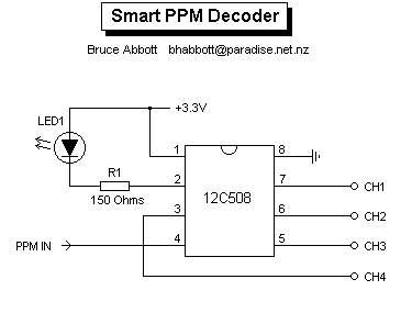
decode.gif [ 3.25 KiB | Прегледано 6309 пъти ]
|
|


 И дали също.


